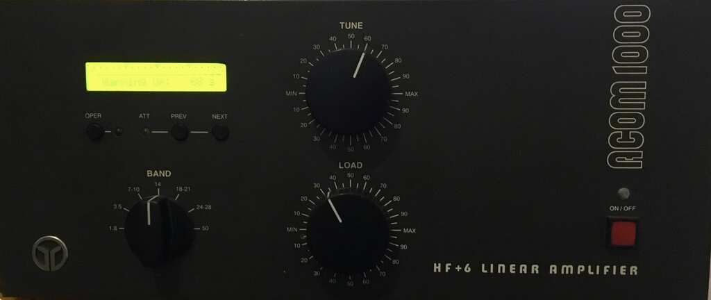
A friend has an ACOM 1000 amplifier. It is used on the HF bands( short wave bands) . It uses one valve for the output and the valve is a Svetlana 4Cx800A. It produces 700-800 watts from a 30 watt input. The valve runs on 3000 volts. You can imagine if something goes wrong in the amp the bang would be BIG ! The designers built a whole load of monitoring circuitry around the valve so that it is shut down if a fault is detected.
A big valve like this needs about 3 minutes to warm up so the monitoring circuit does a count down and locks you out until the valve is up to temperature.
The LCD on the front screen shows the status and you can access the fault codes on the screen. The service guide then enables you to decode the fault codes. This amp was shutting down during the warm up of the valve. The code revealed that there was excessive cathode current. This fault had started appearing occasionally but now the amp was out of service.
As usual I was suspicious that the vale internal insulation was breaking down. It turns out the amp is 15 years old and never had the valve changed. The amp had been well used. So the suspicion was on the valve being at the end of its life. Time to get the outer case and the inner screen off and have a look.
In the picture below you can see the valve in the top right hand side. It is sitting in the red chimney. The valve has all the fins built onto them and a fan forces air up through the fins via the chimney. This is serious mechanical engineering!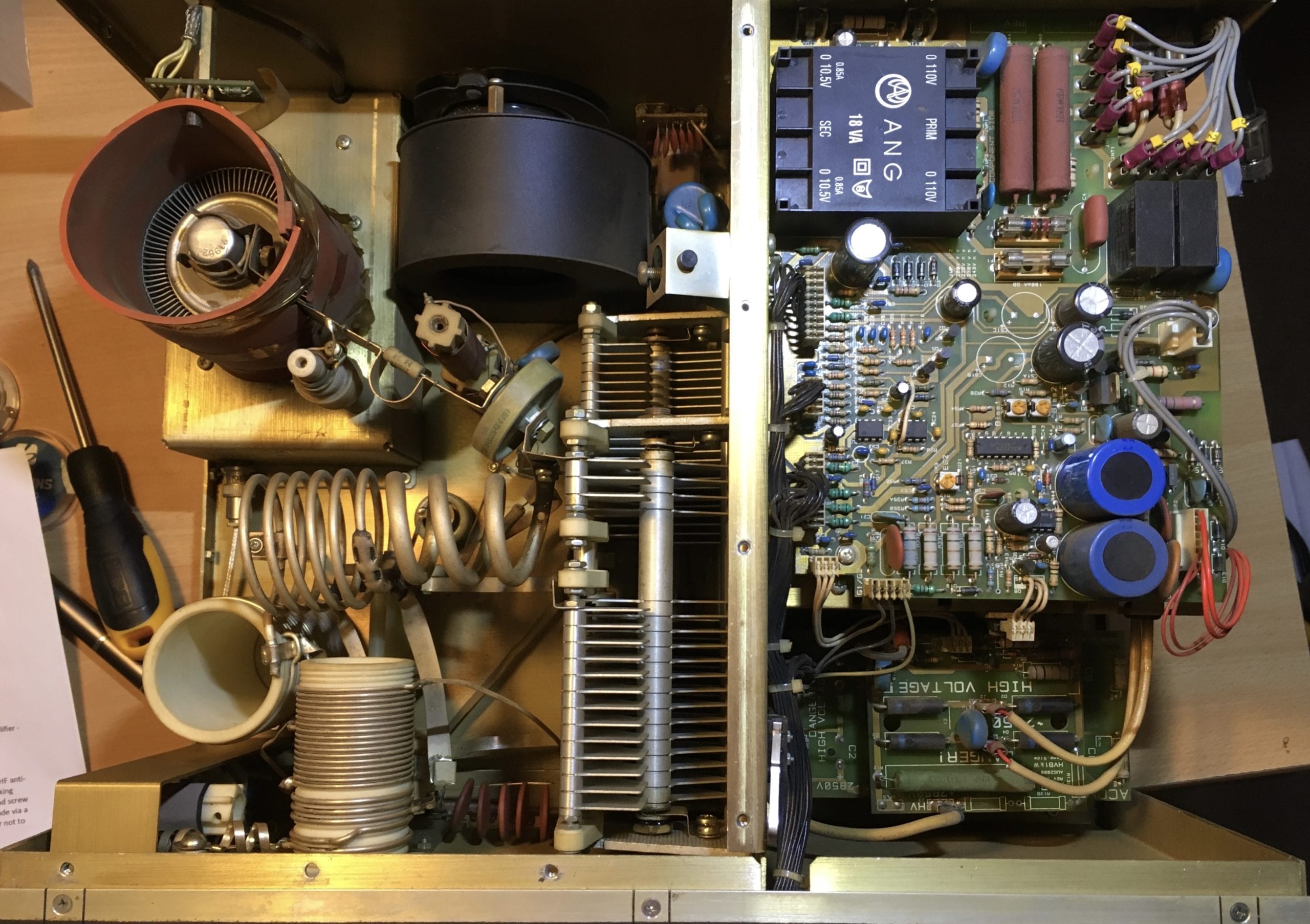
This is more like repairing a car engine rather than working on an amp. Some dismantling was done .
A critically important safety item is to make sure that there are no residual volts on the capacitors. The HT volts runs at 3000 volts so if they are discharged by 90% that still leaves a dangerous 300 volts. This can kill. I used shorting leads to make sure the capacitors were discharged and a final check was on the anode on top of the valve with a multimeter to make sure there really was zero volts
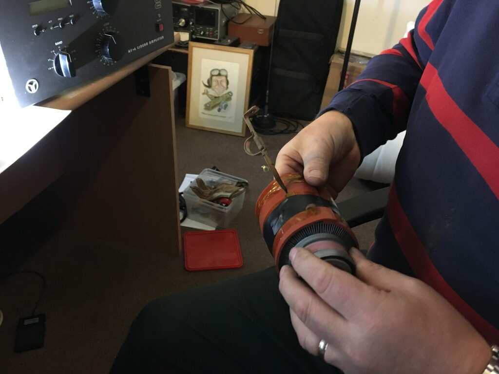
The picture below shows the valve removed and me easing the valve out of the chimney. The metal rod is the connector for the anode which is on top of the valve.
By good luck the owner had a new replacement valve. The 4CX800A valve was made by Svetlana in St Petersburg, Russia. Svetlana is owned nowadays by Electro Harmonix and the valve production was all moved to the Saratov factory. All production of valves stopped in St Petersburg. Production of these high powered transmitting valves ceased. There are some Chinese made close equivalents.
A good quality replacement costs in the region of £400 ( $480) in the UK.
The valve was replaced using spanners and screwdrivers ! . The next step was to set up the bias on the valve for full power operation and for idling. The on board screen shows the bias currents and the two pots to make the adjustments are on the board on the right ( see picture above). These were set to 220mA and 70mA respectively per the amp makers recommendation.
Once I had re-assembled the amp it was time to test it and see what the max power out the amp was now pumping out.
With 25 watts in the output power was 450 watts and increasing the input power achieved 768 watts out. The amp armed up normally and none of the protection circuits cut in.
The owner was astounded to see such a big improvement in power output. This further confirmed the old valve was truly at the end of its life.
An 800 Watt Acom 1000 Valve Amp Fixed!!
We offer a whole range of valves for audio amps . Check out our store
We service and repair amps too and it looks like we have added transmitting valve amps to our kit of expertise . ( and I am the holder of a full amateur radio licence)