Note: We now have a new, superior solution to Marshall JCM2000 hum, noise, and bias drift issues. Find the details here.
Marshall JCM2000 DSL100 Hum after warmup fix
There are a couple of key problems with the Marshall DSL can TSL series printed circuit boards. One is the drifting bias due to board leaking current. This causes the EL34 output valves to overheat,We sell Stable bias board kits for the DSL and the TSL amps which cures this problem
In addition to the bias drift issue in the DSL 50 and 100, TSL401 and 100 models, there is also a problem where the amp hum builds up after warmup. Usually takes fifteen minutes or so before it starts, then gets louder and louder as
the amp warms up.
This is caused by circuit board leakage from the AC heater circuit into
the phase splitter’s (V4) signal lines. The amp already has a DC heater
circuit for V1 and V2. The plan is to feed V3 and V4, the phase splitter with a DC feed too. This will get rid of the hum.
DO NOT ATTEMPT THE FOLLOWING IF YOU ARE NOT TECHNICALLY USED TO WORKING ON PRINTED CIRCUIT BOARDS.
Paul Schmittauer, a highly experienced, amp technician in Albany Ohio, USA wrote down the details on how to fix this issue and took the pictures below. Thank you to our nice customer and friend Paul.
Here is the fix in step-by-step instructions :-
The fix is to convert the AC heater circuit on the Phase splitter to be
DC and so eliminate the AC hum. This will increase the overall DC heater
current.
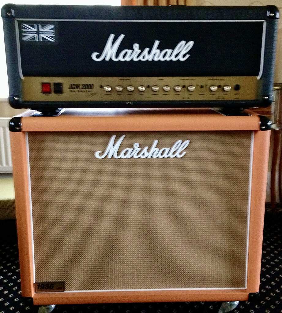
I noted the bridge rectifier used should either be higher rated, or have a heatsink, as the PCB shows heat stress.
I upgraded the bridge to an 8 amp version, which required drilling out the holes in the PCB to accommodate the larger leads. Then we connect the V3 andV4 heaters to the DC circuit, and isolate and abandon the troublesome AC traces on the board.
Referring to the included photos and schematic:
1) Cut the circuit foil under 6.3 amp fuse F1, where it goes to V4 pins
4 and 5. Also cut the other end of the foil, as close to pins 4 and 5 as
possible. I used a Dremel type tool with cutter disk.
2) Cut the V3 heater circuit foil just to the left of the attachment
screw, and again, as close to pins 4 and 5 as possible.
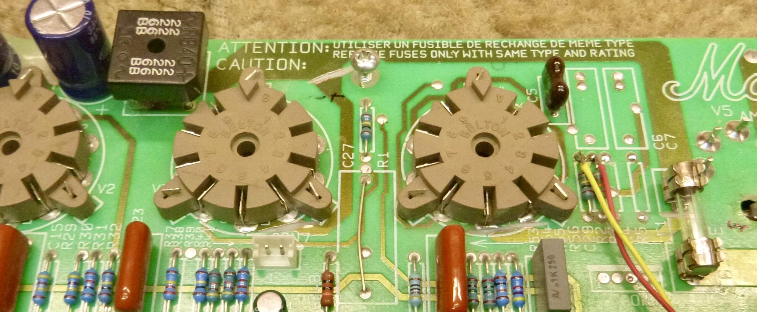
3) Turn the board over and cut the foil between pin 9 of V3 and the
heater buss strip at the edge of the PCB.
4) Do the same to V4, as seen in the photos.
5) Cut about 50mm of hookup wire. Strip about 10mm of one end, and about 2mm of the other.
6) Solder the long end’s tip to the + of the bridge, and bring the bare
part of the wire to pin 9 of V3, soldering it to that point so that the
rectifier’s + is jumpered to V3 pin 9.
7) Bring the other end of this wire to V4 pin 9, and solder it to that pin.
8) Cut another 50mm piece, and strip 2mm on both ends. Solder one end
to the – of the bridge, and the other end to pin 4 of V3.
9) Cut another 50mm piece, strip both ends <> 10 mm, solder one end to
pins 4 and 5 of V4, and the other to pins 4 and 5 of V3.
Double-check your work. I found that this fixed the hum after warmup
problem very effectively, and seems to have the amp making less hum
overall. Why Marshall didn’t do this in the beginning is not known.
We would love to hear your feedback if you have used this modification.
The best solution for JCM2000 hum, noise, and bias drift is replacing the board.