Setting the Bias
There is a lot of discussion on the black magic of setting the bias on the output valves in your amp. This is also related to the matching of the valves.
There is talk of setting the bias “cool” or “hot” and the effects on output valve life. I am attempting to write this so as the musicians can understand and so the idea is that I make it hopefully simple to understand. This is a challenge as my wife tells me that I can make a cheese sandwich sound complicated !
So here goes….
Output valves need to have a certain amount of current flowing through them even when sitting doing nothing. A bit like a car engine needs a certain amount of fuel to run when the car is just sitting. This is to allow the valve to operate in the straight part of the amplification characteristic so that they produce a nice clean sound. Also this affects the amount of power they use. In this example, I will use the figures for the popular 6L6GC as found in Mesa Boogie, Peavey , Fender etc etc etc. The same process is true for EL34‘s , KT66, KT77, KT88, but the numbers will be different according to the maximum power the valve can handle
Most manufacturers state the maximum power the valve can dissipate is 30 watts. Above 30 watts, you will cause them to start glowing dull red ( “red plating”) and they will be cooked to death. Then you can come another set from this website 🙂 , but later be cheesed off as the new set lasted 5 months and you will think I sell rubbish 6L6’s. Let’s see how not to get cheesed off with us !
The biasing is usually set as a maximum of 80% of maximum rated power and 80% of 30 watts is 24 watts. So that seems a good compromise on folks hearing you and not cooking your 6L6’s. Sorry folks here comes a bit of arithmetic but keep reading as it will help give a better sound and save you money.
Power = volts x current. So if we decide to limit the power to 24 watts, then to set the bias current , it is clear we need to know the volts or else we have no idea if we are running the output cold or hot .
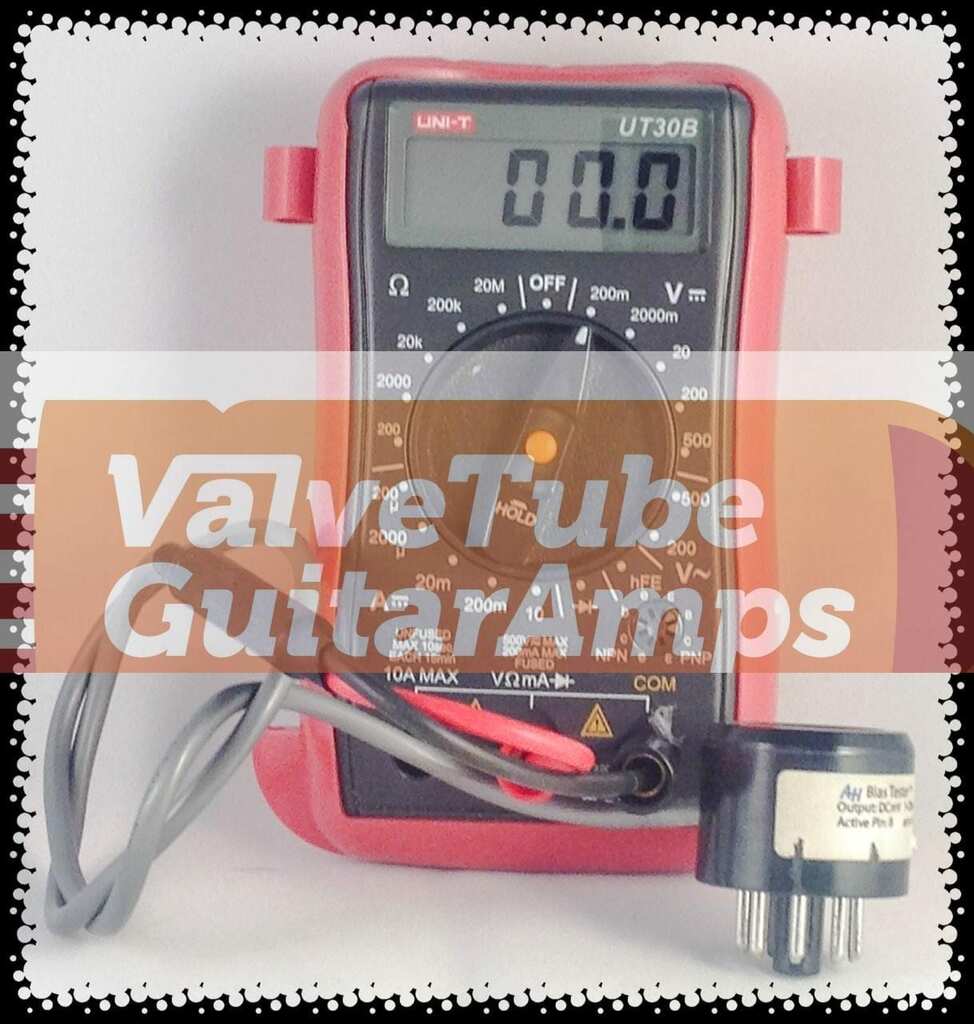
The safest way to set the bias is to use a bias probe. You plug the output valve into the bias probe plug and then plug the valve plus bias probe into the valve socket. See the featured picture for this article. Inside the probe is is just a 1 ohm resistor connected into the anode circuit and all the other connections are just pass through to connect up the valve.
There is a cable coming out and you connect it to a multi=meter. You set the scale to read milli-volts ( mV) so when the anode current is 50 milli-amps ( mA) the meter reads 50 milli-volts. Some bias probes read the current at the cathode but lets not make this more complicated !! We will just discuss anode probing here.
So now we need to know the actual anode voltage. Let’s take the Fender 68 custom Vibrolux as an example. I looked at the schematic of this amp and the high voltage supply for the output valves is 437 volts !! Now that is more than enough to convert you from a musician to a corpse in one blinding flash! So, if you are not qualified , DO NOT go poking in your amp with a voltmeter. Only do this if you intend to leave all your music gear to me in your will. Details can be supplied on request !! Also do not touch the probe wires as they are sitting at high voltage too !!
If you don’t want to go dicing with death, get an amp tech to measure the anode voltage for you.
However, one other simpler and safer approach is to make an estimate. In our Vibrolux example, we know from the schematic, the high tension voltage is 437 volts and we can guess due to losses in the output transformer , we will lose around 25 volts so in this amp, the 6L6’s are running at approximately 400 volts.
For the 6L6 I looked up the data sheet for a number of manufacturers and see that the maximum allowable power is 30 watts. So, I figured running at 70% would be my upper limit I then made up a little table This is in Excel and you can download it . Just click on the picture to download the file.
The spreadsheet is set up to calculate bias for amps using class AB1 mode which is basically what most amp output stages use.
Here is what this simple sheet looks like :
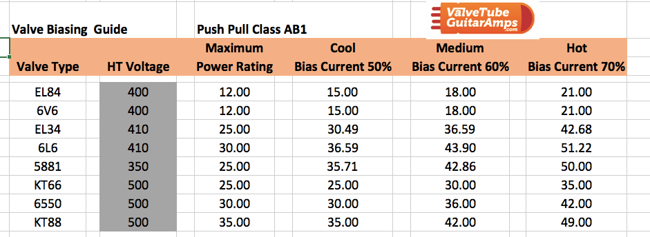
In the grey area you can set the voltage for your amp. If you are not sure just contact us and we can help wth this info
Using the bias probe you can set the bias on each valve by adjusting the pot ( its just a variable resistor. This one pot adjusts the bias current on both valves.
In order to get the closest match, I recommend using a pair of matched valves.
Just one final comment. Make sure your driver valve ( usually an ECC83 in British amps and an ECC81 in American amps) is balanced or else it is almost pointless in having a matched pair of output valves. We sell balanced pre-amp valves and all our valve kits include a balanced phase splitter valve.
So, without knowing the voltage on your valves then trying to set the bias is almost pointless. If you dont want to kill yourself, then drop me an email at info@valvetubeguitaramps.com and I will check schematics and let you know approximately what voltage your amp is running, assuming I can access the schematics.Gee, how did I end up writing about death and destruction when writing about nice music stuff??
There is one other very important aspect of bias setting to consider. I occasionally have calls telling me that the customer has put the valves in his amp and when he checks the bias the valves look is-matched. The reason this happens is that many amps have a one ohm resistor in the cathode and there are terminals for the user/amp tech to measure the milli-volts across this resistor. So id the bias current is to be set to 35mA you should measure 35mV on your meter. Let me give you an example . Customer ” Joe” puts his four brand new matched Tung Sol 6L6GC-STR into his amp and he checks the bias on each of the valves. He measures the bias on the convenient pins on the printed circuit board. He sets the first valve up for 36mA. Then he checks the other three valves and sees up to 40mA !
His conclusion is that the matching is rubbish. Its not even within 10%. He has been ripped off. Not true !!
The big reason he is seeing this variation is because the 1 ohm bias measurement resistors are in the cathode circuit.
He is not just measuring the anode (plate) current. He is actually measuring the anode current + the screen current.
This is what is causing the variation. Valves are matched using the anode current so the only accurate way to set the bias is to measure the anode current only.This means putting the 1 ohm resistor in the anode circuit and not the cathode circuit. In the real world setting up your amp using the cathode current is good enough as long as you know you have a matched set of output valves ( hopefully with the test results to show the matching).
You might ask why do the amp manufacturers not put the resistor in the anode( plate) circuit as this is the more accurate way to set up the amp? The reason is that the anode connections sit up at the highest voltage in the amp and usually north of 400 volts. If you put easy access pins on the amp chassis, it is inviting you to have a shocking experience if you accidentally touch the pins. The bias measuring resistor in the cathode is safe and sits at a few volts.
It is also worth remembering that the 1 ohm resistors will not be exactly the same value as they have a tolerance on them. If they are 1% resistors then one of them could be 1% high and the other 1% low so there can be a variation of 2% just due to the resistors that you are measuring the bias current !!
The key message here is that if you have a bias measuring tool, check if it is measuring anode or cathode current.
Happy playingand good luck on setting the bias in your amp! remember you are dealing with high voltages so take extreme caution!!
As always just email us or phone us with any questions. we are always happy to help.
We sell matched output valves in singles, pairs and quads from JJ , EHX, Genalex, Sovtek and Tung Sol. We match them on Avo testers to within 4% and supply a test certificate showing the test conditions and matching parameters of anode current and Gm.
The Black Magic of Setting the Bias make your amp sound its best