Quick Intro to the Fender Bassbreaker 007
The Fender Bassbreaker 007 is a cute little valve amp. There are two versions – a head and a combo. It has two 12AX7 pre-amp valves and one EL84 output valve. It has a 10 inch Celestion speaker. A nice compact practice amp. Check it out on the Fender website.
Fender quotes this amp as 7 watts audio output in the manual. It does not say whether this is RMS or peak. By comparison, the Vox AC4 uses exactly the same valve line up and quotes 4 watts. An EL84 is rated as 7.5 watts maximum so Fender is pushing the EL84 to the limit.
The Red Plating Issue
However this Fender Bassbreaker 007 amp had an issue. The owner originally bought a replacement EL84. However, it was red plating. Starting to look like a red traffic light.
Normally red plating output valves are a result of under biasing so let’s look at the biasing circuit.
Amp Construction
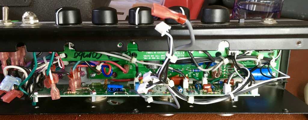
This is a compact amp and Fender has squashed three printed boards into a small space. This results in a load of connectors between the printed circuit boards and makes dismantling a bit slower. The designers did not consider the repairability of this amp as their top priority.
1st Attempt at Repair
The EL84 is cathode biased with a the usual resistor and decoupling capacitor to ground. The decoupling capacitor was open circuit. There are no schematics available from fender as this amp is a current product. However the EL84 class A output stage is a very standard circuit. Someone had previously badly replaced the cathode resistor decoupling capacitor with a radial leaded device and this was replaced with a radial capacitor. Aha methinks a cure!
Alas no!
Fixing the amp permanently
So the amp was partially re-assembled so I could safely test it. The red plating I thought had initially disappeared so I was happy. However after roughly 5 minutes there was the ominous dull red glow. Blast ! Luckily, the amp was improved but still remnants of the issue was still there!
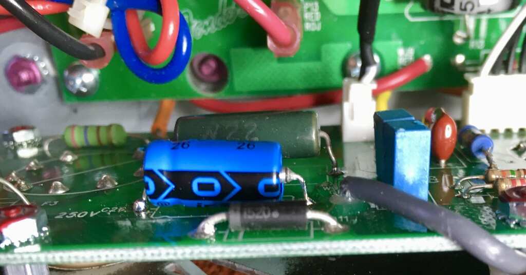
The cathode 5 watt resistor was a bit cooked on the underside and everything was connected up ok. No dry joints. But hang on – the resistor value appeared to be 165ohms ! For one lonely EL84 this is way under-biasing ! Normally I it should be somewhere in the region of 300-400ohms ! The only way the EL84 will not overheat is when it is a poor emission valve.
Further investigation revealed that the 30 volt zener diode had gone leaky. I was reading 330 ohms in either direction. The 330 ohm bias resistor and the diode in parallel is creating a 165 ohms cathode bias resistor The diode was replaced and now the EL84 is happy and now that it is correctly biased. The cooked cathode resistor was replaced with a good quality Vishay 330Ohm resistor.
Suggested Valve Kit
The ideal quality replacement valve kit for this amp which has a pair of Sovtek 12AX7WA medium gain valves and a Sovtek EL84
Conclusion
I reckon that the original EL84 developed a short circuit and blew the zener. This is also the reason the bas resistor was a bit cooked. Again the lesson is do not leave EL84’s in amp for too long unless you want to give folks, like me, money to sort out the collateral damage. Timely replacement of valves is always the cheaper option, and moreover, your amp will always sound nice!